Introduction
For decades, calibration certificates have been the central means of communication between the calibration laboratory and the user. They document traceable measurement results, measurement uncertainties, and relevant boundary conditions—however, in practice, they are almost always provided as PDFs and are therefore primarily intended for human interpretation. For databases, LIMS systems, or automated evaluations, this information can only be used with considerable additional effort.
With the Digital Calibration Certificate (DCC), a standardized, XML-based format has been available for several years that represents calibration information in a structured and machine-readable way. In the meantime, both cross-measurement conventions and subject-specific expert reports exist, creating a resilient framework for practical implementation—including in temperature calibration.
Many laboratories are thus faced with a very specific question: How can established processes and proven calibration certificates be transferred into this world without introducing additional complexity into everyday laboratory life?
This article examines this transition from the perspective of a temperature calibration laboratory. The focus is on resistance thermometers according to DKD-R 5-1 and the question of how the contents of a classic calibration certificate can be consistently found in a structured digital calibration certificate—from the temperature scale used and environmental conditions to self-heating and hysteresis.
Content
Motivation
At first glance, the established world of PDF calibration certificates works reliably: the customer receives a document, can understand the table with measured values and uncertainties, and archives the file in the QM system. However, it becomes critical the moment calibration data needs to be further processed—for example, for automatic transfer into a test equipment management system, for trend analyses, or for comparing multiple calibrations over time.
The cause lies in the nature of the format: a PDF contains no explicit measurement quantities, no clearly interpretable units, and no structured metadata. The information contained therein is easily readable for humans, but accessible to machines only with considerable additional effort.
This is exactly where the Digital Calibration Certificate comes in. A Digital Calibration Certificate does not merely document in continuous text that a Pt100 was calibrated at 100 °C, but stores this information in clearly defined data structures—including measuring equipment, scale used, reference, influencing factors, and uncertainty contributions. This enables evaluations that today often still require manual transfers, copy-and-paste processes, or OCR-based workflows.
In temperature calibration in particular, the step towards structured representation is obvious. Technical details such as temperature scales, calibration media, self-heating, or hysteresis must be carefully recorded anyway. If this information is available in machine-readable form, both sides benefit: laboratories can use data consistently, and users receive a resilient basis for long-term analyses.
The motivation for this article is therefore to transfer the often abstract-seeming Digital Calibration Certificate to a concrete and everyday calibration topic. The transition from the classic PDF certificate to the digital calibration certificate proves to be less of a technological upheaval and more of a consistent structuring of what is already being measured and documented in qualified laboratories today.
What is the DCC?
The Digital Calibration Certificate is a standardized, XML-based data format for describing calibrations. In contrast to the classic PDF, the focus is not on the typographic representation, but on a clearly defined data structure in which all relevant information is stored in machine-readable form—from the serial number of a probe and the temperature scale used to individual measured values and their uncertainties.
The most important source is the PTB page on the Digital Calibration Certificate. There, the Physikalisch-Technische Bundesanstalt describes the DCC as a digital evolution of the classic calibration certificate and as an XML-based format for structured information.
The PTB page from the Innovation Cluster for Digitalization explains why XML is important: it states that the DCC is based on XML, is machine-readable, and that information can be transferred directly into digitally supported processes. It also mentions the role of cryptographic signatures for integrity and authenticity.
Formally, the digital calibration certificate is based on an XML schema maintained by the Physikalisch-Technische Bundesanstalt (PTB). This schema defines the available elements, their relationships to each other, and mandatory and optional content. Examples include administrativeData for administrative key data or measurementResults for the actual calibration results. In addition, the DCC Wiki serves as a detailed reference for structure, semantics, and practical implementation.
The PTB’s DCC Good Practice Wiki is very valuable because it bundles concrete good practice content and XML examples from the collaboration between industry, calibration laboratories, and the PTB.
A key design principle is its measurement-neutrality. Regardless of whether a calibration comes from the fields of mass, pressure, electrical quantities, or temperature, the same structural framework is used. Only through subject-specific conventions—for example, in the form of DKD expert reports—do concrete recommendations for the respective measurement quantity emerge.
For temperature calibration, these specifications concern in particular the unambiguous specification of temperature scales, the description of the calibration medium, and the structured recording of typical influencing factors. These aspects will be addressed specifically in the following sections.
Focus of this article
The subject area surrounding the digital calibration certificate is broad. In addition to cross-measurement conventions, there are different schema versions, extensive wiki documentation, and subject-specific recommendations for various calibration areas. For practical laboratory work, however, it is neither necessary nor expedient to consider all aspects simultaneously. This article therefore deliberately sets a clearly defined focus.
The focus is on temperature calibration with resistance thermometers according to DKD-R 5-1. This guideline is established in many laboratories and forms a stable basis for considering structured calibration data. Building on this, the DKD expert report DKD-E 5-3 specifies how a technically consistent digital calibration certificate for temperature measurement quantities can be designed.
In the following, the following questions in particular are addressed:
- How is a calibration item—consisting of a probe, display, or complete measuring chain—consistently structured in
items? - How can temperature scales, for example ITS-90 or thermodynamic temperature, be stored in a way that is unambiguous and interpretable in the long term?
- Where are influencing factors such as self-heating, hysteresis, measuring current, and ambient conditions mapped?
- How can a typical result table according to DKD-R 5-1 (reference value, display, measurement deviation, uncertainty) be transferred to
measurementResults?
This article is expressly not intended as a complete introduction to the DCC schema. Rather, the goal is a practical translation of the abstract structures of a digital calibration certificate into a comprehensible application scenario from daily temperature calibration. The article is therefore aimed in particular at laboratories planning to start using the DCC or wishing to further develop existing processes in a structured manner.
Structure of a digital calibration certificate
A Digital Calibration Certificate is not a freely structured XML document, but follows a clearly defined, modular structure. The overall structure can be divided into logically delimited areas—from unchangeable administrative key data and technical measurement results to optional additions.
In essence, this system also corresponds to the content-related order of a classic calibration certificate: first the formal information, then the measurement results, and finally supplementary information. The DCC transfers this proven structure into a consistently machine-readable model.
The specific XML structure is defined in the official schema (currently version 3.3.0) and in the accompanying documentation of the DCC Wiki. Each of these areas is represented by a parent element, whose sub-elements determine which content is mandatory and which can be optionally added.
The PTB publication on the use of the DCC schema explains that the DCC, as an XSD/XML schema, represents a kind of template for digital calibration certificates and requires technical specifications for specific measured quantities.
The four “rings”
The root element digitalCalibrationCertificate is divided into four main areas that build on each other both functionally and logically. This structure supports a consistent separation between administrative information, technical results, and supplementary content, and contributes significantly to the machine-interpretability of the document.
Ring 1: administrativeData – Administrative basis of the calibration
This area includes all stable and unchangeable information regarding the calibration. This includes, among other things, the calibration laboratory, customer, responsible persons, a unique identification of the calibration certificate, and the calibration item itself—including manufacturer information, serial numbers, and system description.
For temperature calibrations, the structured description of the measuring system in items is particularly relevant. Here, even complex configurations, such as probes as subItems of a data logger, can be clearly modeled. In addition, normative references, for example to DKD-R 5-1, and accreditation information can be stored.
Since this information is largely independent of the measurement quantity, the generic character is particularly evident in this ring.
Ring 2: measurementResults – Technical core of the certificate
The actual calibration results are mapped in the measurementResults area. Each measurementResult forms a logically coherent measurement block and links results with methods, measuring equipment, and influencing conditions.
Typical components are:
- calibration methods used (
usedMethods, e.g., DKD-R 5-1) - measuring equipment used (
measuringEquipments, such as thermostats or reference thermometers) - documented influencing conditions (
influenceConditions) - the measurement results themselves, represented as
quantityor structuredlist
For resistance thermometers, a classic result table with reference temperature, display, measurement deviation, and expanded uncertainty can be transferred directly into such a list. Semantic classifications via refType, for example basic_referenceValue or temperature_selfHeating, ensure that the meaning of individual values remains clearly interpretable.
This ring thus forms the metrological focus of the entire DCC.
Ring 3: comment – Extensions and supplementary information
The comment area serves as a deliberately flexible container for content that does not necessarily have to be assigned to administrative data or measurement results. This can include, for example, photos of the measurement setup, graphical representations of characteristic curves, or exported raw data.
Structured data can also be integrated here, for example via additional quantity elements or XML blocks with their own namespaces. For laboratories, this opens up the possibility of linking evaluation artifacts directly with the reported results, thereby further increasing traceability.
Ring 4: document – Human-readable representation
Embedding a human-readable representation of the calibration certificate is optional, but recommended in practice. This is often done as a PDF/A, and in the future also as an HTML-based variant.
In this way, the DCC remains immediately usable even if the recipient does not have XML processing capabilities. The structured data representation and the familiar document thus complement each other instead of competing.
In addition, the entire certificate can be cryptographically signed using ds:Signature. Electronic seals or qualified time stamps enable traceable safeguarding of integrity and authenticity.
Important basic concepts
The understanding of a Digital Calibration Certificate is based on a few but fundamental structural principles. These include the formal XML architecture, the semantic linking via refType, and the use of the Digital SI to describe quantitative values. These concepts apply regardless of the measurement quantity and form the technical basis for consistent and machine-interpretable calibration documentation. In temperature calibration, they are further specified by subject-specific conventions, including those from DKD-E 5-3.
XML structure, namespaces, and links
A digital calibration certificate is an XML document that is validated against a defined XSD schema. This validation ensures that the structure and content remain clearly interpretable and prevents inconsistent data models.
Central attributes within the schema are:
id(xs:ID) for the unique identification of an element, for example a proberefId(xs:IDREFS) for referential linking, for example between a measured value and a calibration itemrefType(refTypesType) for the semantic classification of content, for examplebasic_referenceValuefor reference values ortemperature_ITS-90to identify the temperature scale used
In particular, the refTypes are crucial for the machine-interpretability of a DCC. While general classifications are defined in the “basic” namespace, subject-specific extensions—for example for temperature or humidity—are described in corresponding expert recommendations and maintained via controlled vocabularies.
For temperature calibrations, namespaces such as temperature are used, potentially supplemented by further differentiating classifications in the future.
Digital SI (D-SI) for values and uncertainties
All quantitative data within a digital calibration certificate is described via the Digital SI namespace (si:). This model enables a structured representation of numerical values including unit and measurement uncertainty.
Typical forms are:
- Individual values as
si:realwithsi:valueandsi:unit - Series of measurements via
si:realListXMLList - parallel units, such as Kelvin and degrees Celsius, via
si:hybrid - Uncertainties as
si:expandedUncertaintyorsi:standardUncertainty
For example, a reference temperature can be stored in both degrees Celsius and Kelvin. This redundancy-free multiple representation facilitates subsequent numerical processing, for example when applying evaluation equations.
Role of DCC-Wiki and DKD expert reports
The schema structure itself is comprehensively documented by the DCC Wiki and thus functions as a technical reference for structure, elements, and validation rules. Building on this, DKD expert reports formulate concrete application recommendations for individual measurement quantities.
Particularly relevant are:
- DKD-E 0-3 as a cross-measurement good practice recommendation
- DKD-E 5-3 with specific guidelines for temperature and humidity measurement quantities, including refTypes, scale specifications, and typical influencing factors such as self-heating or hysteresis
In summary, the DCC can be understood as a structured construction kit. The generic elements provide a stable foundation, while subject-specific additions ensure that even metrological peculiarities can be described precisely and unambiguously.
Special requirements for temperature calibration
Temperature calibration places special requirements on the structured description of calibration data. This is due to metrological peculiarities such as the unique assignment to temperature scales, the selection of suitable calibration media, and the consideration of characteristic influencing factors such as self-heating or hysteresis. These aspects have a direct influence on measurement results and uncertainty budgets and therefore require precise and unambiguously interpretable documentation.
While the schema is deliberately designed to be generic, such measurement-specific requirements are specified by technical conventions. For temperature and humidity measurement quantities, this role is assumed by the DKD expert report DKD-E 5-3 (“Instructions for using the DCC schema for temperature and humidity measurement quantities”), which describes how typical metrological facts can be consistently transferred into a machine-readable structure.
The following sections take up these recommendations and use central elements to show how the peculiarities of temperature calibration can be professionally mapped within the DCC.
Temperature scales and their significance
Temperature is one of the physical quantities whose measured value cannot be fully interpreted without reference to the underlying scale. In addition to thermodynamic temperature—defined via the Boltzmann constant—there are practical temperature scales such as ITS-90, PLTS-2000, and the historical IPTS-68. These represent high-precision realizations, but are not identical.
Specifying the unit Kelvin alone is therefore not sufficient. A digital calibration certificate must clearly state which temperature scale a reference value refers to so that subsequent evaluations, comparisons, or conversions can be carried out correctly from a technical perspective.
Mapping in the DCC according to DKD-E 5-3
The scale used is coded via subject-specific refTypes within the temperature namespace, for example:
temperature_temperatureThermodynamic– thermodynamic temperaturetemperature_ITS-90– International Temperature Scale of 1990temperature_PLTS-2000– scale for low temperaturestemperature_IPTS-68– historical temperature scale
Example of a reference temperature within a quantity:
<dcc:quantity refType="basic_referenceValue temperature_ITS-90">
  <si:hybrid>
    <si:valueXMLList><si:real>373.15</si:real></si:valueXMLList>
    <si:unitXMLList><si:unit>kelvin</si:unit></si:unitXMLList>
  </si:hybrid>
</dcc:quantity>
Representation of measurement results
Measurement results form the technical core of every calibration certificate. In a digital calibration certificate, this area also becomes the element in which the structural added value of the digital representation is particularly evident. While a PDF essentially provides a visual table, the DCC describes reference values, displays, measurement deviations, and uncertainties as semantically classified data objects.
Central building blocks are quantity elements, which are uniquely linked to numerical values, units, and uncertainties via the Digital SI (D-SI).
Basic structure of a measurement result
Quantitative data is fundamentally stored within <quantity refType="…">, whereby the refType determines the technical meaning. Typical classifications are:
basic_referenceValue– reference temperature, for example from a thermostatbasic_indicationValueorbasic_measuredValue– display or measured value of the test itembasic_measurementError– measurement deviation as the difference between reference and display
This semantic assignment ensures that the interpretation of a value does not depend on the table context, but emerges directly from the data structure.
Digital SI for precise quantitative data
The si namespace enables a consistent representation of numerical information, regardless of whether individual values or series of measurements are available. Typical forms are:
- Individual values via
si:realwithsi:valueandsi:unit - Series of measurements via
si:realListXMLList - parallel units, such as Kelvin and degrees Celsius, using
si:hybrid - Uncertainties as
si:expandedUncertaintyorsi:standardUncertainty
Example of a reference temperature:
<dcc:quantity refType="basic_referenceValue temperature_ITS-90">
  <si:hybrid>
    <si:valueXMLList>
      <si:real><si:value>373.15</si:value></si:real>
    </si:valueXMLList>
    <si:unitXMLList>
      <si:unit>kelvin</si:unit>
      <si:unit>degreecelsius</si:unit>
    </si:unitXMLList>
  </si:hybrid>
</dcc:quantity>
Ambient conditions
Ambient conditions are among the essential influencing factors in temperature calibration. Parameters such as laboratory temperature, relative humidity, or air pressure can either enter directly into the uncertainty budget or must be documented to ensure traceability.
In the digital calibration certificate, this information is mapped in a structured way via <influenceCondition refType="basic_ambient">, with each influencing factor listed as its own <quantity>. This ensures that environmental parameters remain clearly identifiable and can be included in further analyses if necessary.
Typical specifications in the temperature range
- Ambient temperature (often in the range of 20 °C to 25 °C)
- Relative humidity (typically around 40% to 60% RH)
- Air pressure, if metrologically relevant, for example in cryogenic applications
Coding as an interval
In classic calibration certificates, the ambient temperature is often specified as an interval, such as “(23 ± 1) °C”. In the digital calibration certificate, this information can be modeled as a uniform distribution, with half the interval width being converted into a corresponding standard uncertainty.
<dcc:influenceCondition refType="basic_ambient">
  <dcc:quantity refType="temperature_ITS-90">
    <si:real>
      <si:value>296.15</si:value>
      <si:unit>kelvin</si:unit>
      <si:expandedUncertainty>
        <si:value>0.577</si:value>
        <si:coverageFactor>1.732</si:coverageFactor>
      </si:expandedUncertainty>
    </si:real>
  </dcc:quantity>
</dcc:influenceCondition>
Specification of the calibration medium
The calibration medium used is one of the decisive influencing factors in temperature calibration. Heat transfer, stability, and homogeneity of the medium have a direct effect on measurement results and uncertainties. Accordingly, clear documentation is a prerequisite for the professional interpretation of calibration data.
For example, a resistance thermometer shows different behavior in a stirred oil bath than in a dry block or in air. Without explicit specification of the medium, neither resilient conclusions about operating conditions nor a consistent uncertainty assessment are possible.
Figure DKD-E 5-3
In the DCC, the description of the calibration medium takes place within measuringEquipments using the refType basic_calibrationMedium. The use of controlled vocabularies is recommended to ensure a uniform and machine-interpretable classification.
| DCC Name | German | Physical state | Typical application |
|---|---|---|---|
air | Air | gaseous | Thermostat, climatic chamber |
water | Water | liquid | Liquid bath |
oil | Oil | liquid | Stirred oil bath |
nitrogen_gas | Nitrogen (gaseous) | gaseous | Cryogenic applications |
liquid | Liquid (generic) | liquid | Medium not further specified |
Example coding (oil bath)
<dcc:measuringEquipment refType="basic_calibrationMedium">
  <dcc:equipmentClass refType="basic_equipmentClass">
    <dcc:scheme>DKD-E-5-3 Medium List</dcc:scheme>
    <dcc:classId>oil</dcc:classId>
  </dcc:equipmentClass>
</dcc:measuringEquipment>
The calibration item: Resistance thermometers according to DKD-R 5-1
Resistance thermometers—including Pt100, Pt25.5, or Standard Platinum Resistance Thermometers (SPRTs)—are among the established reference instruments in temperature calibration. With DKD-R 5-1, a widely used guideline exists for this, formulating detailed requirements for the description of the probe, display, measuring chain, and relevant parameters.
In the digital calibration certificate, the calibration item is modeled within administrativeData via the items structure. This structure is deliberately designed to be flexible and enables the mapping of both individual probes and complex measuring systems with multiple channels.
Why detailed modeling is required
In practice, a calibration item is rarely an isolated component. Often, a complete measuring chain is present, consisting of a probe, connection cable, and display or logging unit. For metrological traceability, these components must be clearly identifiable so that measurement results can later be assigned without doubt—for example, to a specific channel or sensor.
The structured description of the measuring system is therefore not merely a formal requirement, but a prerequisite for consistent and long-term interpretable calibration data.
Key structure: items
The data model distinguishes between several levels:
itemsdescribes the overall system, including higher-level information such as designation, manufacturer, or owner.itemrepresents individual components, for example probes or display units.subItemsenable hierarchical modeling, for example if several probes are assigned to a data logger.
Each item is assigned a unique id, to which measurement results can refer via refId. This establishes a consistent connection between the calibration object and the result data.
DKD-E 5-3 explicitly recommends not listing internal laboratory aids such as multimeters or adapters as part of the calibration item. Instead, they are documented in the measuringEquipments area, maintaining the clear separation between the test item and the measurement technology used.
The following subsections show examples of how a typical Pt100 measuring system according to DKD-R 5-1 can be mapped within this structure.
Quantitative properties of the probe
In addition to manufacturer information, model designation, and serial number, DKD-R 5-1 also requires the documentation of quantitative parameters of the probe. These are unchangeable parameters from the data sheet that are relevant both for uncertainty considerations and for the long-term reproducibility of calibrations.
In the digital calibration certificate, these properties are modeled centrally within the respective probe item via itemQuantities. The individual specifications are described as primitiveQuantity with Digital SI values and subject-specific refTypes and are thus clearly classified.
Typical refTypes according to DKD-E 5-3
| refType | Meaning | Example value | Unit |
|---|---|---|---|
temperature_probeType | Probe type (qualitative) | Pt100 | – |
temperature_probeDiameter | Probe sheath diameter | 2.3 | mm |
temperature_itemCableLength | Connection cable length | 1.5 | m |
basic_nominalValue | Nominal resistance at 0 °C | 100 | Ω |
Example coding (Pt100 as subItem of a logger)
<dcc:item id="fuehler_pt100_01">
  <dcc:name><dcc:content>Pt100 Fühler</dcc:content></dcc:name>
  <dcc:description>
    <dcc:content refType="temperature_probeType">Manteltyp, 4-Leiter</dcc:content>
  </dcc:description>
  <dcc:itemQuantities>
    <dcc:itemQuantity refType="temperature_probeDiameter">
      <si:real><si:value>2.3</si:value><si:unit>millimetre</si:unit></si:real>
    </dcc:itemQuantity>
    <dcc:itemQuantity refType="temperature_itemCableLength">
      <si:real><si:value>1.5</si:value><si:unit>metre</si:unit></si:real>
    </dcc:itemQuantity>
    <dcc:itemQuantity refType="basic_nominalValue">
      <si:real><si:value>100</si:value><si:unit>ohm</si:unit></si:real>
    </dcc:itemQuantity>
  </dcc:itemQuantities>
</dcc:item>
Administrative data for calibration
The administrative data forms the stable framework of a Digital Calibration Certificate. It contains the information that, independently of the actual measurement results, ensures the formal identity, traceability, and verifiability of a calibration. In temperature calibration, too, this information is largely standardized and is based on normative requirements, including those from DKD-R 5-1 and ISO/IEC 17025.
Within the DCC, this information is located in the Ring 1 area administrativeData.
Key elements in coreData
<dcc:coreData>
  <dcc:countryCodeISO3166_1>DE</dcc:countryCodeISO3166_1>
  <dcc:usedLangCodeISO639_1>de</dcc:usedLangCodeISO639_1>
  <dcc:usedLangCodeISO639_1>en</dcc:usedLangCodeISO639_1>
  <dcc:mandatoryLangISO639_1>de</dcc:mandatoryLangISO639_1>
  <dcc:uniqueIdentifier>TK-2026-00123</dcc:uniqueIdentifier>
  <dcc:receiptDate>2026-02-01</dcc:receiptDate>
  <dcc:beginPerformanceDate>2026-02-15</dcc:beginPerformanceDate>
  <dcc:endPerformanceDate>2026-02-15</dcc:endPerformanceDate>
  <dcc:performanceLocation>laboratory</dcc:performanceLocation>
</dcc:coreData>
These core data ensure the unique identifiability of a calibration certificate and create the prerequisite for audit-proof documentation.
Laboratory data and responsible persons
Other central elements concern the performing laboratory and the responsible technical personnel:
calibrationLaboratory– Information about the laboratory, including address and accreditation statusrespPersons– responsible persons with role description, optional signature function, and assignment as main signatory (mainSigner="true")customer– full identification of the client
This information is not only formal in nature, but forms the basis for responsibility and legal assignability.
Normative declarations in statements
Via statements, statements valid for the certificate can be stored that apply to the entire certificate. Typical contents are:
- Declaration of standard conformity, for example a calibration according to DKD-R 5-1 in conjunction with ISO/IEC 17025
- Information on metrological traceability to national standards and thus to the International System of Units (SI)
- Accreditation texts, for example in the context of multilateral agreements such as EA or ILAC
Example of an accreditation declaration:
<dcc:statement refType="accreditation">
  <dcc:norm>ISO/IEC 17025:2018</dcc:norm>
  <dcc:declaration>
    <dcc:content>Der Kalibrierschein dokumentiert die Rückführbarkeit auf nationale Normale...</dcc:content>
  </dcc:declaration>
</dcc:statement>
Measurement-specific additions
Initial measurement-specific information can already appear at the administrative level, for example references to DKD-R 5-1 or the temperature scale used. Furthermore, the unique identifier (uniqueIdentifier) and date specifications are considered normative minimum requirements according to ISO/IEC 17025.
Significance for laboratory practice
A large part of this information is already available in structured form in modern laboratories, often within a LIMS or order system. The digital calibration certificate transfers this data into a consistent, machine-readable format and thereby enables automated assignments—for example, between the calibration certificate and the test item.
Administrative data is thus much more than formal accompanying information: it forms the organizational foundation of technically resilient calibration documentation.
Mapping measured values and parameters
Measurement results form the technical core of every calibration certificate. Accordingly, their structured representation in the DCC is of central importance. Unlike classic certificates, in which results are often available as static tables or embedded documents, they are modeled in the DCC as structured measurementResults and are thus immediately available for machine processing.
For resistance thermometers according to DKD-R 5-1, this specifically means: A typical calibration table with several temperature points is mapped as list with parallel quantity columns. In addition, information on the methods applied, measuring equipment used, and relevant influencing factors can be consistently integrated.
The DKD expert report DKD-E 5-3 describes in detail how analog result representations can be transferred into such machine-readable structures. In addition to the actual characteristic curve, this also includes additional parameters such as input value or self-heating, which are often documented separately or merely textually in classic calibration certificates.
This transforms measurement results from a primarily visual representation into clearly structured data objects. This structure forms the basis for automated evaluations, long-term comparability, and consistent integration into digital quality assurance processes.
Result structure in measurementResults
Each measurementResult maps a logically related result block, for example a main characteristic curve or the determination of self-heating. Within this container, both the boundary conditions of the calibration and the actual measurement data are brought together in a structured manner.
Framework information
Several elements define the metrological context of the subsequent results:
usedMethods– guidelines applied, such as DKD-R 5-1, as well as internal work instructionsmeasuringEquipments– measurement technology used, such as thermostats, reference thermometers, or measuring bridgesinfluenceConditions– relevant influencing factors, for example immersion depth, measuring current, or calibration mediummeasurementMetaData– global metadata such as traceability or conformity statements
This structured context description ensures that measurement results are not considered in isolation, but always remain interpretable in connection with the conditions under which they were created.
Result representation
The measurement data itself can be stored in two basic forms:
- Individual values as
quantity, for example for input values - Table structures as
listwith several parallelquantitycolumns
Example structure of a characteristic curve table
<dcc:measurementResult>
  <dcc:usedMethods>
    <dcc:usedMethod refType="basic_calibrationMethod">DKD-R 5-1</dcc:usedMethod>
  </dcc:usedMethods>
  <dcc:list refId="fuehler_pt100_01">
    <dcc:quantity refType="basic_referenceValue temperature_ITS-90">
      <!-- Referenzwerte als si:realListXMLList -->
    </dcc:quantity>
    <dcc:quantity refType="basic_indicationValue">
      <!-- Anzeigewerte -->
    </dcc:quantity>
    <dcc:quantity refType="basic_measurementError">
      <!-- Messabweichungen einschließlich Unsicherheit -->
    </dcc:quantity>
  </dcc:list>
</dcc:measurementResult>
Typical result table of a PRT
In practice, a characteristic curve calibration according to DKD-R 5-1 usually ends in a table with reference temperatures (e.g., 0 °C, 100 °C, 200 °C), the associated display values of the Pt100 (in Ω or °C), the deviation, and the expanded uncertainty U(k=2). In the DCC, this table is mapped as list. The columns are listed as parallel quantity elements, each with its own refType. This makes the meaning of each column unambiguous without a human having to read the table header.
Analog vs. DCC – direct comparison:
| Reference [°C] | Display [Ω] | Deviation [mK] | U(k=2) [mK] |
|---|---|---|---|
| 0,000 | 100,012 | +12 | 8 |
| 100,000 | 138,522 | -5 | 12 |
| 200,000 | 175,834 | +18 | 15 |
DCC mapping (abbreviated, 3 points):
<dcc:list refId="fuehler_pt100_01">
  <!-- Spalte 1: Referenz (ITS-90) -->
  <dcc:quantity refType="basic_referenceValue temperature_ITS-90">
    <si:realListXMLList>
      <si:valueXMLList>
        <si:real><si:value>273.15</si:value></si:real>  <!-- 0°C -->
        <si:real><si:value>373.15</si:value></si:real>  <!-- 100°C -->
        <si:real><si:value>473.15</si:value></si:real>  <!-- 200°C -->
      </si:valueXMLList>
      <si:unitXMLList><si:unit>kelvin</si:unit></si:unitXMLList>
    </si:realListXMLList>
  </dcc:quantity>

  <!-- Spalte 2: Anzeige (Widerstand) -->
  <dcc:quantity refType="basic_indicationValue">
    <si:realListXMLList>
      <si:valueXMLList>
        <si:real><si:value>100.012</si:value></si:real>
        <si:real><si:value>138.522</si:value></si:real>
        <si:real><si:value>175.834</si:value></si:real>
      </si:valueXMLList>
      <si:unitXMLList><si:unit>ohm</si:unit></si:unitXMLList>
    </si:realListXMLList>
  </dcc:quantity>

  <!-- Spalte 3: Abweichung inklusive U(k=2) -->
  <dcc:quantity refType="basic_measurementError">
    <si:realListXMLList>
      <si:valueXMLList>
        <si:real><si:value>0.012</si:value></si:real>   <!-- +12 mK -->
        <si:real><si:value>-0.005</si:value></si:real>  <!-- -5 mK -->
        <si:real><si:value>0.018</si:value></si:real>   <!-- +18 mK -->
      </si:valueXMLList>
      <si:unitXMLList><si:unit>millikelvin</si:unit></si:unitXMLList>
      <si:expandedUncXMLList>
        <si:realList><si:value>0.008</si:value></si:realList>  <!-- U(k=2) -->
        <si:coverageFactor>2</si:coverageFactor>
      </si:expandedUncXMLList>
    </si:realListXMLList>
  </dcc:quantity>
</dcc:list>
Important details:
• Parallel units are possible: Reference additionally in °C via si:hybrid
• refId: Uniquely links the result table with the probe ID
• Uncertainty: Directly assigned to the deviation and listed as a temperature quantity (e.g., mK)
• Scale specification: temperature_ITS-90 is explicitly stated at the reference value, not just implicitly in the text
Laboratory practice:
In essence, the structure maps exactly what is typically calculated and documented in Excel today. The difference is that the assignment no longer has to be derived from the column position, but is semantically contained in the data set. A script can take the table directly from the measurement software, and an evaluation immediately recognizes: Column 1 is reference, Column 3 is deviation.
This enables applications that are difficult to implement with PDF documents: trend analyses over several years, automated conformity checks, or a quick comparison of individual temperature points, for example if the deviation at 200 °C shifts systematically.
Input value and insulation resistance
In addition to the characteristic curve, DKD-R 5-1 requires two supplementary tests: the input value (resistance at 0 °C or at the triple point of water) and the insulation resistance. Both are not table values, but independent measurement results with their own traceability and often separate uncertainty. In the DCC, they are therefore listed as dedicated quantity elements outside the main list.
Input value (temperature_inputValue):
The resistance of a Pt100 at 0 °C (273.15 K) forms the reference point for subsequent conversions and characteristic curve evaluations. DKD-R 5-1 requires traceable traceability for this as well as the specification of the
measurement uncertainty.
DCC mapping:
<dcc:measurementResult>
  <dcc:usedMethods>
    <dcc:usedMethod>DKD-R 5-1, Abschnitt 5.1</dcc:usedMethod>
  </dcc:usedMethods>
  <dcc:quantity refType="temperature_inputValue">
    <si:real>
      <si:value>100.005</si:value>  <!-- gemessener Wert -->
      <si:unit>ohm</si:unit>
    </si:real>
    <si:expandedUncertainty>
      <si:value>0.002</si:value>    <!-- U(k=2) -->
      <si:coverageFactor>2</si:coverageFactor>
    </si:expandedUncertainty>
    <dcc:measurementMetaData refType="basic_metrologicallyTraceableToSI">
      <dcc:declaration>Rückführbar auf nationale Normale</dcc:declaration>
    </dcc:measurementMetaData>
  </dcc:quantity>
</dcc:measurementResult>
Insulation resistance:
This test serves to verify sufficient electrical insulation, for example, to prevent short circuits or leakage currents.
A minimum value is usually required, such as >100 MΩ, tested at the minimum and maximum calibration temperatures.
The schema does not recognize direct operators such as “>” or “≥”. DKD-E 5-3 therefore recommends storing measured minimum values explicitly as numerical values. The technical interpretation is then carried out via the
underlying specification.
DCC mapping (simplified):
<dcc:quantity refType="temperature_insulationResistance">
  <si:realListXMLList>
    <si:valueXMLList>
      <si:real><si:value>150</si:value></si:real>  <!-- Min-T: 150 MΩ -->
      <si:real><si:value>120</si:value></si:real>  <!-- Max-T: 120 MΩ -->
    </si:valueXMLList>
    <si:unitXMLList><si:unit>megaohm</si:unit></si:unitXMLList>
  </si:realListXMLList>
</dcc:quantity>
Laboratory practice:
In traditional calibration certificates, this information often appears as a marginal note or footnote. In the DCC, however, the input value and insulation resistance are documented as independent, traceable measurement results with
the associated method. This allows automated tests to be supported, such as whether an input value is within defined tolerances or whether minimum insulation requirements are met.
Precise referencing via Methods down to the section level further increases traceability and facilitates subsequent evaluations.
Self-heating and measurement current
Self-heating (heating of the sensor caused by the measurement current) is a classic uncertainty contribution for resistance thermometers. DKD-R 5-1 identifies three cases:
- Measured (recommended),
- Estimated (e.g., from literature),
- Flat-rate contribution (30 mK as a rectangular distribution → standard uncertainty 17 mK).
In the digital calibration certificate, it is mapped as a separate quantity refType="temperature_selfHeating"—including
metadata on whether it was measured and whether it is included in the uncertainty budget.
Measurement current:
The set current (typically 1 mA for Pt100) is documented as influenceCondition refType="temperature_measuringCurrent".
DCC mapping (measured self-heating):
<dcc:quantity refType="temperature_selfHeating">
  <si:real>
    <si:value>0.025</si:value>  <!-- 25 mK gemessen -->
    <si:unit>millikelvin</si:unit>
  </si:real>
  <si:standardUncertainty>
    <si:value>0.014</si:value>  <!-- Standardunsicherheit -->
  </si:standardUncertainty>
  <dcc:measurementMetaData>
    <dcc:property refType="temperature_isMeasured">true</dcc:property>
    <dcc:property refType="temperature_isInUncertainty">true</dcc:property>
  </dcc:measurementMetaData>
</dcc:quantity>

<!-- Messstrom als Einflussbedingung -->
<dcc:influenceCondition refType="temperature_measuringCurrent">
  <dcc:quantity>
    <si:real><si:value>1.0</si:value><si:unit>milliampere</si:unit></si:real>
  </dcc:quantity>
</dcc:influenceCondition>
Flat-rate case (common):
Value = “NaN” (no specific measured value), only uncertainty (17 mK from 30 mK rectangular distribution):
<si:value>NaN</si:value>
<si:standardUncertainty><si:value>0.017</si:value></si:standardUncertainty>
Laboratory practice:
Today, this is often a text note (“Self-heating of 30 mK taken into account”). In the DCC, the contribution is explicitly quantified and provided with metadata—essential for traceable uncertainty budgets. The machine can check: “Was self-heating measured? Is it included in U?” This saves time during audits or customer inquiries and minimizes
interpretation errors.
Hysteresis and other influences
Hysteresis describes the temperature difference at the same reference temperature but in the opposite direction (upwards/downwards). DKD-R 5-1 requires its determination and consideration—analogous to self-heating. In the DCC, it is assigned its own quantity refType="temperature_hysteresis" with identical logic:
value, uncertainty, and metadata.
DCC structure (analogous to 5.4):
<dcc:quantity refType="temperature_hysteresis">
  <si:real>
    <si:value>0.008</si:value>  <!-- 8 mK hysterese -->
    <si:unit>millikelvin</si:unit>
  </si:real>
  <si:standardUncertainty>
    <si:value>0.005</si:value>
  </si:standardUncertainty>
  <dcc:measurementMetaData>
    <dcc:property refType="temperature_isMeasured">true</dcc:property>
    <dcc:property refType="temperature_isInUncertainty">false</dcc:property> <!-- separat berichtet -->
  </dcc:measurementMetaData>
</dcc:quantity>
Metadata flags:
temperature_isMeasured: Was hysteresis actively determined?temperature_isInUncertainty: Is the contribution already included in the
reported expanded uncertainty?
Not measured? Value = “NaN”, only uncertainty (e.g., flat-rate from literature).
Other typical influences (briefly):
- Timestamp: Per measured value as
<dateTimeXMLList>(ISO 8601)
—documents sequence and time (optional, but useful for drift). - Immersion depth: In
usedMethodQuantitiesastemperature_immersionDepth(critical for heat dissipation). - Statements of conformity: In
measurementMetaDatawithconformity="pass"per point or globally.
Laboratory practice:
Hysteresis is often only roughly estimated or omitted. In the DCC, the structure forces a clear decision—measured or flat-rate? And: separate or in U? This increases transparency and facilitates subsequent analyses (“Hysteresis > 10 mK → consider replacement”). With refId, everything links seamlessly to the sensor and main characteristic curve.
Implementation in the laboratory
The previous sections have shown how a DCC for temperature calibrations is structured. However, the decisive step is the practical implementation: How does a laboratory transfer its existing
Excel spreadsheets, evaluation software, and work instructions into a valid DCC? This section outlines the workflow from the analog PDF certificate to the machine-readable DCC—with a focus on realistic feasibility.
From the analog certificate to the digital calibration certificate
Initial situation in many laboratories:
The measurement data comes directly from the calibration software. In the spreadsheet, reference values, displays, deviations, and uncertainties are then evaluated using formulas. The final report is created in a word processor or LaTeX as a PDF—with embedded tables and graphics. Administrative data such as customer information, date, or serial number come from the LIMS or are entered manually.
How it gets into the DCC:
The structure is taken directly from the templates—admin data from LIMS, tables from Excel, individual special values added, graphics/PDF attached.
Use templates:
DKD-E 5-3 contains complete XML examples for Pt100 calibrations in Annex A/B. Use these as a starting point and overwrite fields—instead of starting from scratch.
Result: 30 minutes of PDF creation becomes 5–10 minutes of DCC generation + validation. The DCC does not replace the PDF, but supplements it with machine usability.
A conclusion on the state of affairs
The DCC is not an abstract XML experiment, but a tool that brings exactly the information density of an analog calibration certificate into a machine-readable form—especially for temperature calibrations
with their scale, medium, and influence nuances. The most important points:
- Structured mapping: From the sensor description
(items) to characteristic curve tables (list) to
self-heating and hysteresis—all with semanticrefTypes
and D-SI. - Added value through precision: Explicit scales
(temperature_ITS-90), metadata (“included in uncertainty?”), and
links (refId) make DCCs directly evaluable. - Feasible in the laboratory: With mapping from Excel/LIMS and templates from
DKD-E 5-3, getting started is straightforward.
The DCC thus marks the next logical step after PDF certificates: away from static documents toward structured data sources that enable trend analyses, conformity checks, and automation.
For temperature laboratories, the timing is favorable—the technical building blocks are ready. Anyone who starts with a Pt100 example usually gains practical experience quickly.
Sources
[1] Digital Calibration Certificate DCC
Physikalisch-Technische Bundesanstalt (PTB)
https://www.ptb.de/cms/metrologische-dienstleistungen/dkd/dkd-dcc.html[file:16]
[2] DCC Wiki (as of: 2026-01-08)
https://dccwiki.ptb.de[file:17]
[3] DKD-E 5-3: Instructions for using the DCC schema for the creation of a digital calibration certificate for temperature and humidity measurands
https://www.ptb.de/cms/fileadmin/internet/dienstleistungen/dkd/archiv/Publikationen/Expertenberichte/DKD-E_5-3_DCC_Rev0_de.pdf[file:16]
[4] DKD-R 5-1: Calibration of resistance thermometers
(referenced in DKD-E 5-3 and PTB documentation)[file:16]
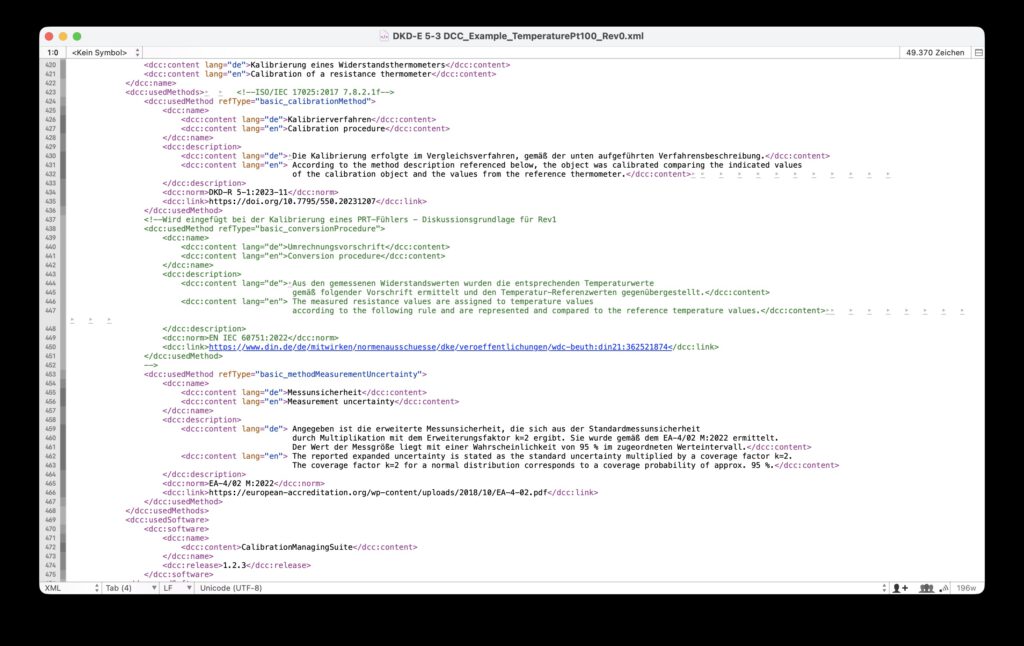
Header image source: Screenshot from the XML sample file in DKD-E 5-3, Annex A (PTB).